A detailed list of topics covered here: https://drive.google.com/drive/u/0/folders/10cdRMwWBwlZej5zEHk7ZxPRo2hF2fUU8
Workplace skills and safety
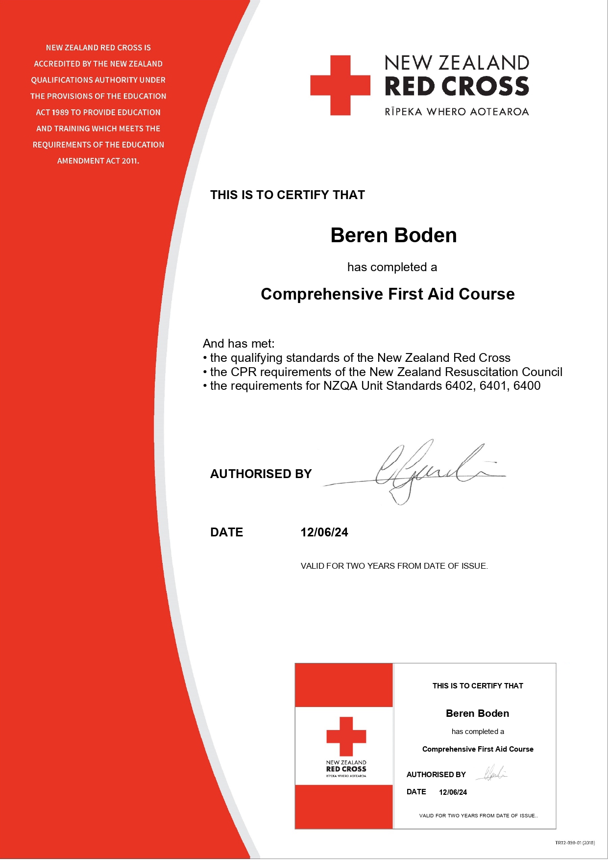
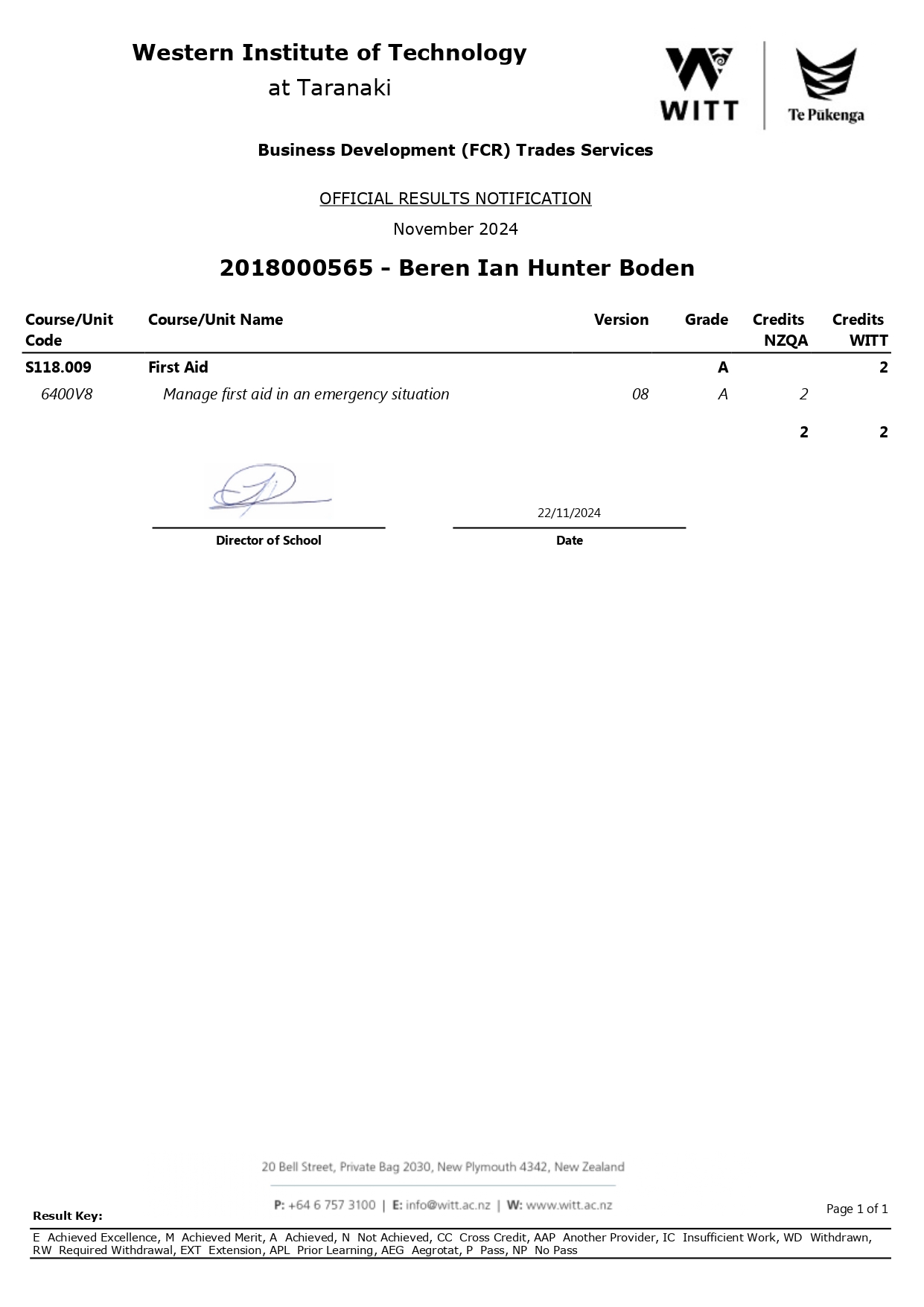
In this course, we learned about workplace safety, electrical hazards, protective measures, legal frameworks, employment relations fire safety, and governance standards in the electrical industry. We also attended a first aid course where we achieved the requirements for NZQA Unit Standards 6402, 6401, and 6400.
DC fundamentals
This course taught us foundational mathematical skills, electrical concepts, and circuit calculations. It also taught me many of the fundamental theories in circuits and electronics. This has been a significant help and a great foundation for further learning about electronics.
The final question in our theory assessment:
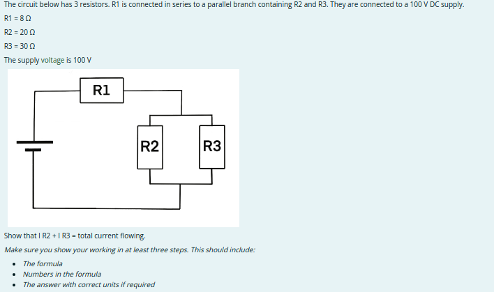
- Rp = 1 / (( 1 / R2) + (1 / R3))
- 1 / (( 1 / 20) + (1 / 30)) = 12
- Rp = 12 Ohms
Calculate the total resistance of the circuit (Rt) including R1 and Rp:
- Rt = R1 + Rp
- 8 + 12
- Rt = 20 ohms
Find the total current (It) using Ohm's law and the total resistance of the circuit:
- It = V / Rt
- 100 / 20
- It = 5 Amps
Calculate the individual currents flowing through each resistor in the parallel branch:
- I_R2 = It * (R3 / (I_R2 + I_R3))
- 5 * (30 / (20 + 30)) = 3
- I_R2 = 3 Amps
- I_R3 = It * (R2 / (I_R2 + I_R3))
- 5 * (20 / (20 + 30)) = 2
- I_R3 = 2 Amps Answer: This means that I_R2 + I_R3 = 5 Amps, which is equal to the total current flowing (It = 5 Amps)
AC Fundamentals
The AC Fundamentals course covered magnetism, electromagnetism, AC/DC systems, electrical tools, safety procedures, and practical applications in electrical work and testing.
We learned about the fundamentals of magnetism and electromagnetism, their uses in devices like motors, relays, and transformers, and the generation and properties of AC and DC currents. We also covered critical AC calculations, including impedance and transformer operations, and proper safety procedures for isolating circuits and using test instruments. Additionally, we gained practical knowledge of selecting, using, and maintaining electrical tools for safe and effective electrical work.
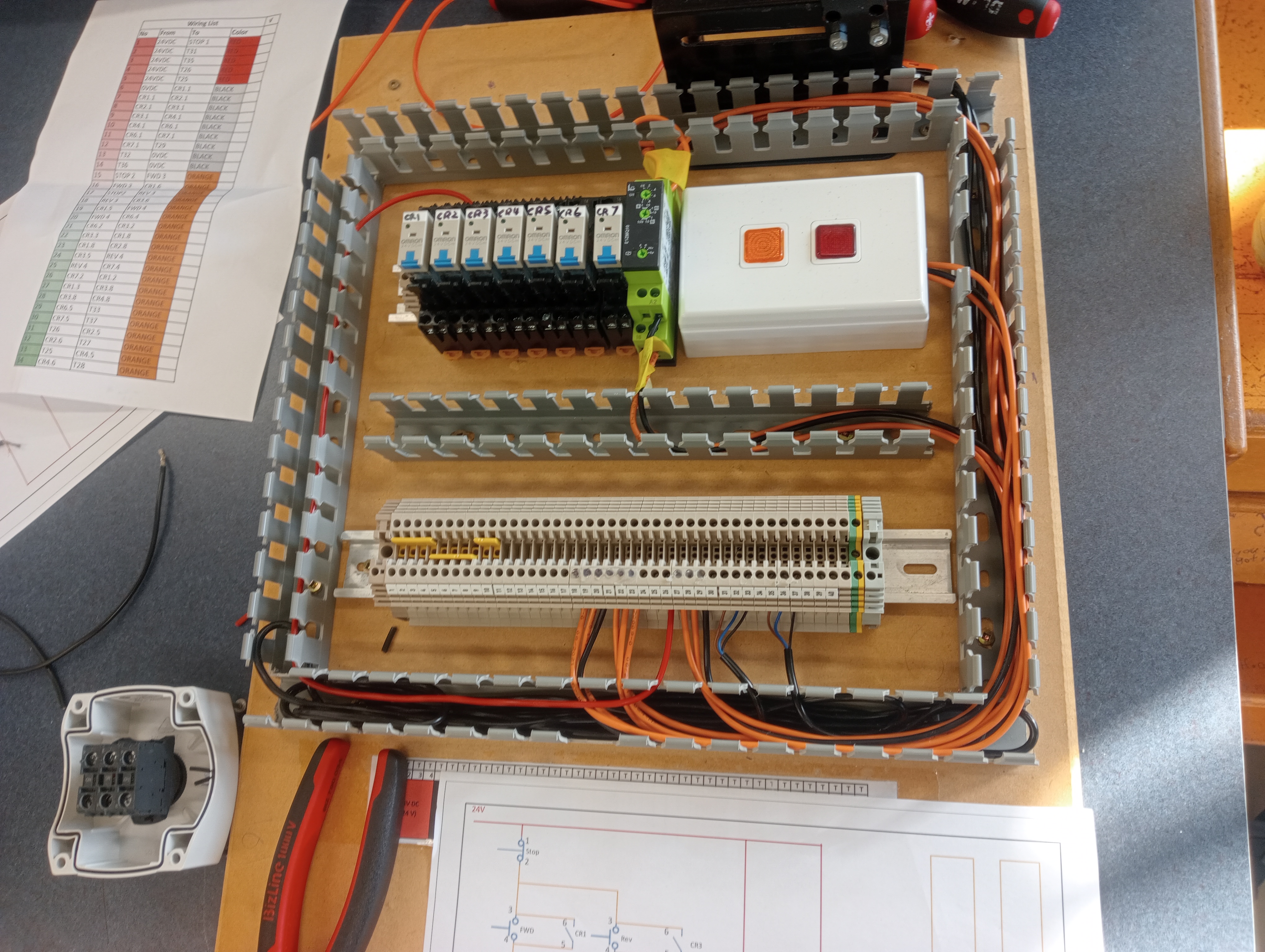
This was a practical exercise. We had to follow an electrical schematic to create a magnetizing and demagnetizing door opening contact.
Cables, fittings, and testing
This topic taught us about, the installation, testing, and protection of cables and fittings, addressing environmental and mechanical factors, fault diagnosis, and practical assessments involving various materials and fixings.
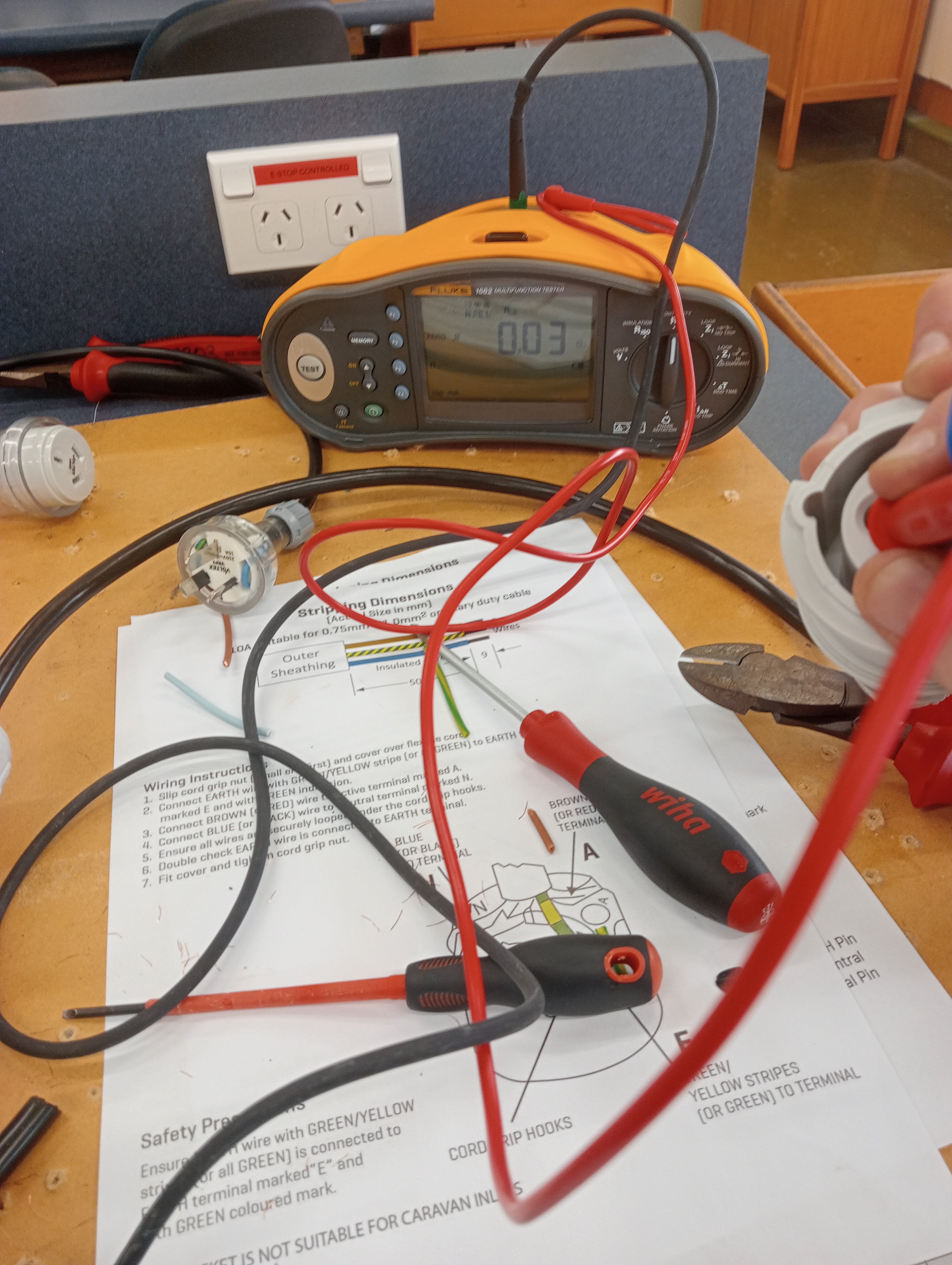
We learned how to select and install cables based on electrical ratings and environmental conditions, perform insulation and continuity testing with tools like the Fluke 1662, and understand how to protect cables from damage. We looked at mechanical and environmental factors like bending, temperature, and fire resistance, following standards like AS/NZS 3000. We also learned about electrical faults, their causes, and symptoms, including open circuits, short circuits, and earth leakage. The practical assessment involved using fixings like spring toggle anchors on materials like timber, GIB, and fiber cement board, ensuring secure installations.
Supply systems
Supply systems fundamentals focused on the components, functions, installation, and testing of earthing systems, along with fault-loop impedance calculations and bonding requirements for safety.
We learned how the earthing system works, including the purpose and installation of the earth electrode, main earthing conductor, and protective earthing conductor. We covered equipotential bonding to prevent voltage differences in metalwork, segregation of services, and testing methods like earth fault-loop impedance to ensure protective devices operate correctly. Calculations showed how issues like poor connections can impact fault current and safety.
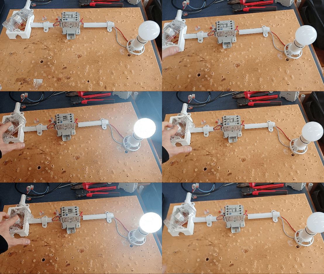
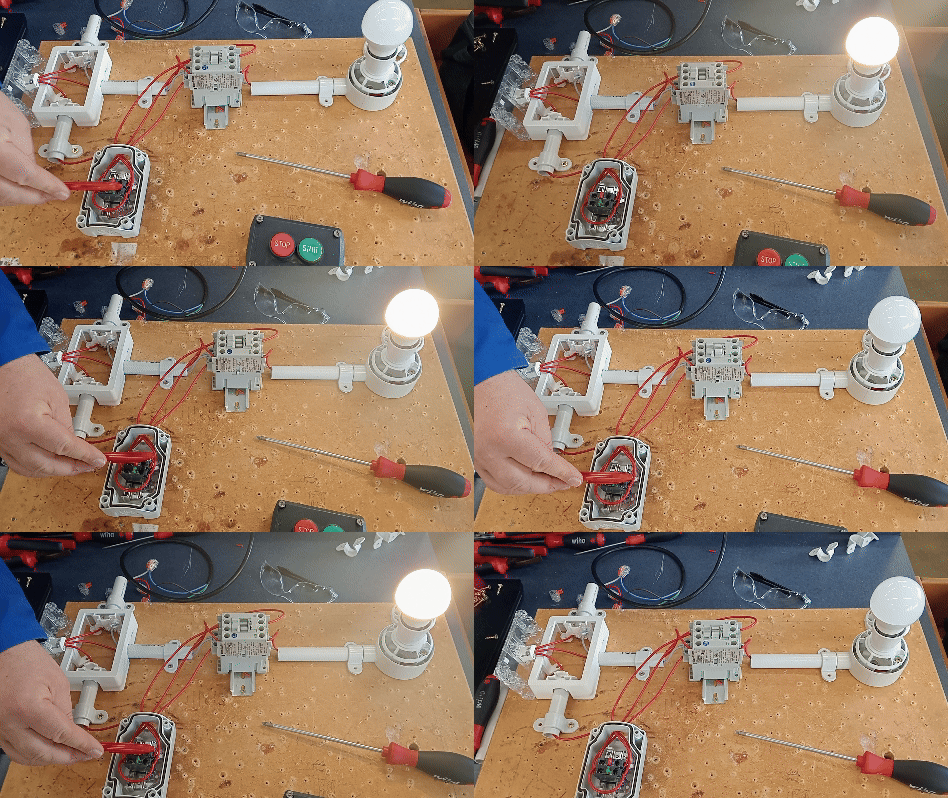
The video below shows a contactor we each made which is operated by a switch, when the switch is closed, the contactor will energize the coil and close the circuit to allow the flow of high-current AC safely and efficiently. This is different from a relay you will find in small DC circuits mainly used for electronics.
Protection, Plans, and Circuits
This course covered circuit protection devices, electrical drawings, power switching circuits, and lighting systems, focusing on their principles, applications, selection, installation, and design.
We learned about the construction, operation, ratings, and applications of circuit protection devices like fuses and RCDs, including their classifications and how to install replacements. We covered how to select and install these devices, including in hazardous areas, to meet legislative requirements. Electrical drawing conventions and symbols were used to create accurate electrical diagrams. We designed and built power switching circuits and covered the principles, design, and installation of different lighting systems.
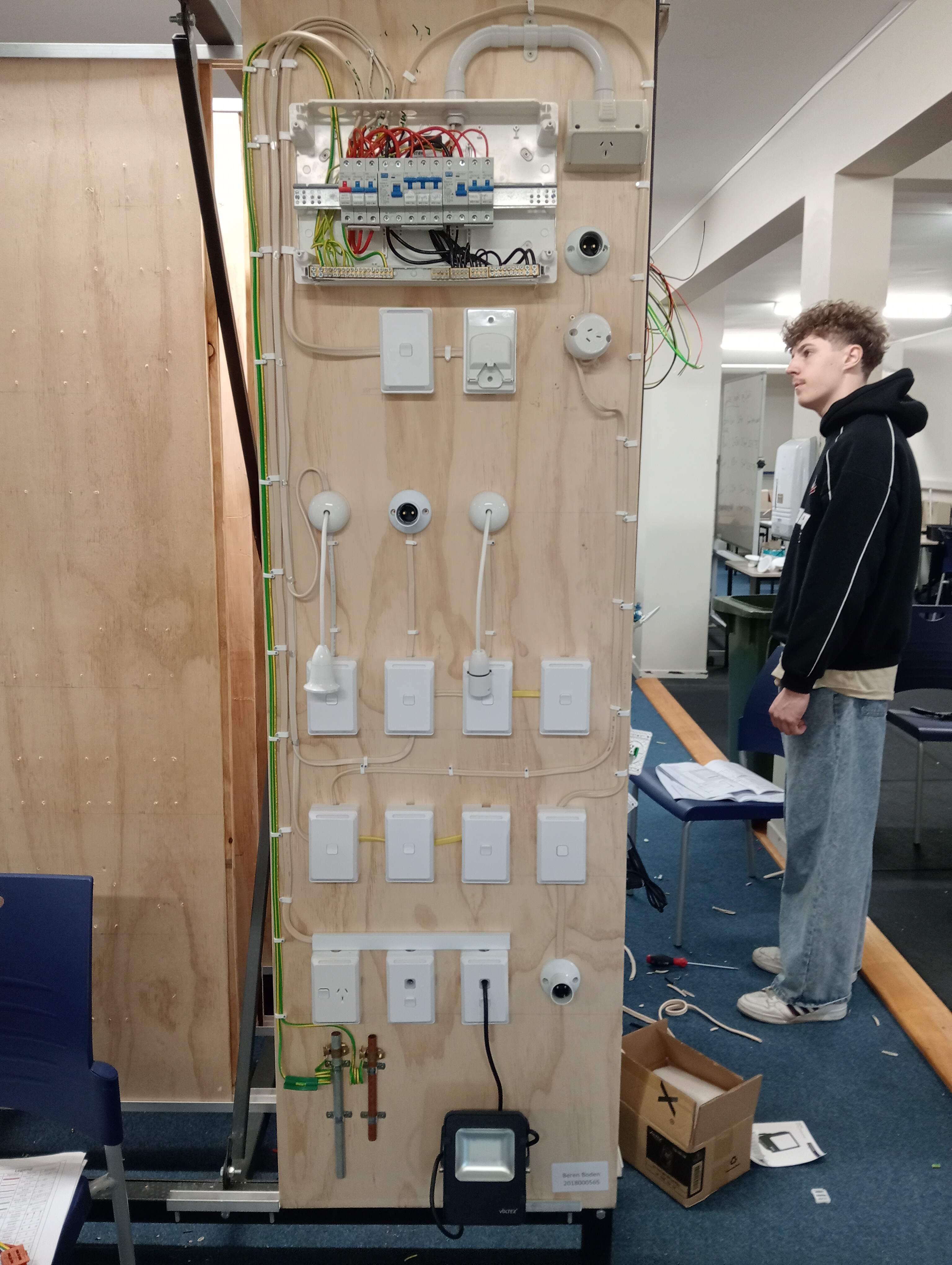
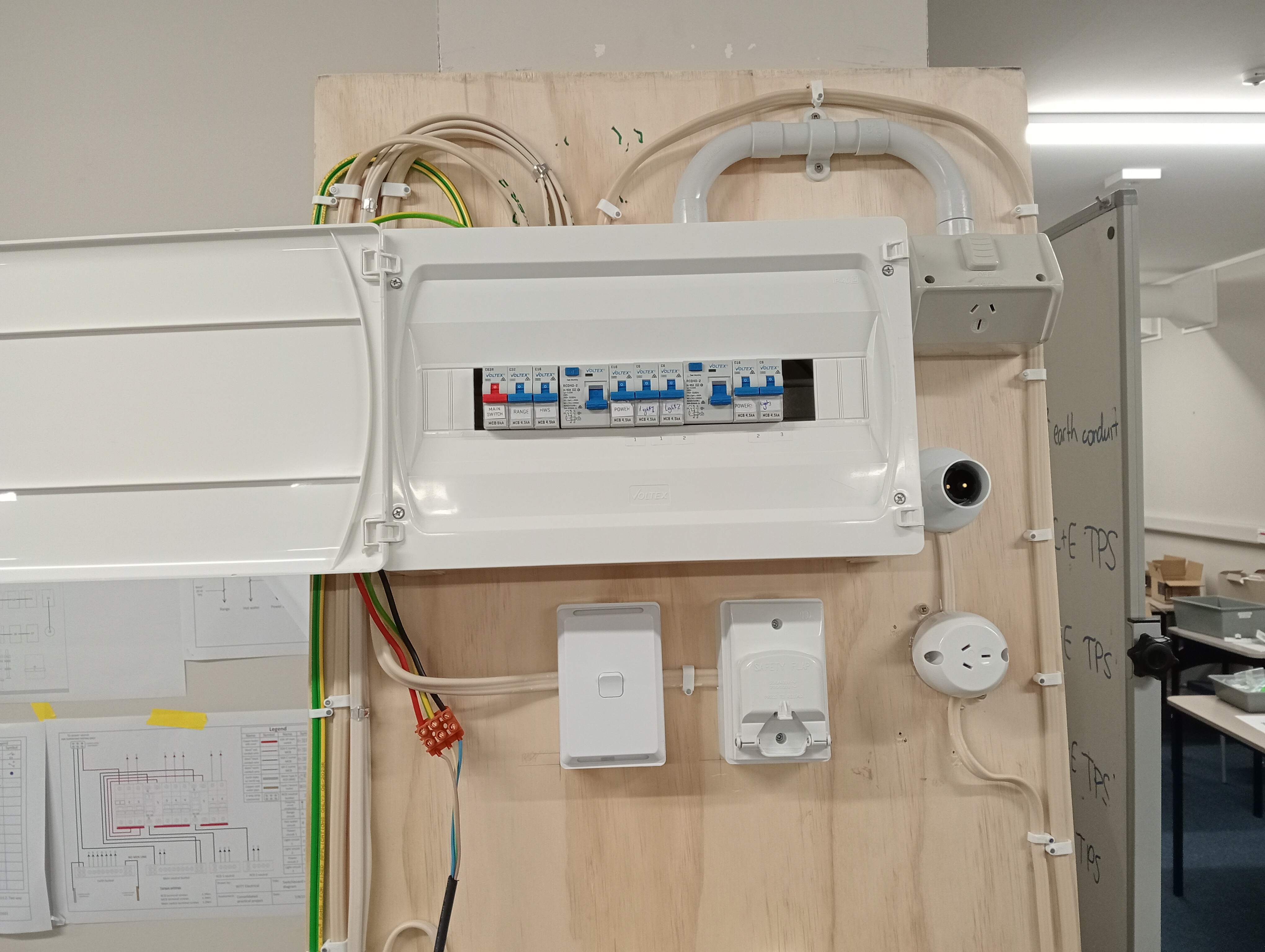
This included the biggest practical assessment we did which was creating a domestic circuit. Individually on a 2x0.8m piece of ply, we each wired 6A lighting circuits which included one-way switches, 2-way switches, intermediate switches, a ceiling rose, an ES lamp holder lighting fixture, BC light fitting, 16A power circuits, a 32A range circuit, and a 16A IP53 outlet which was for a hot water cylinder.
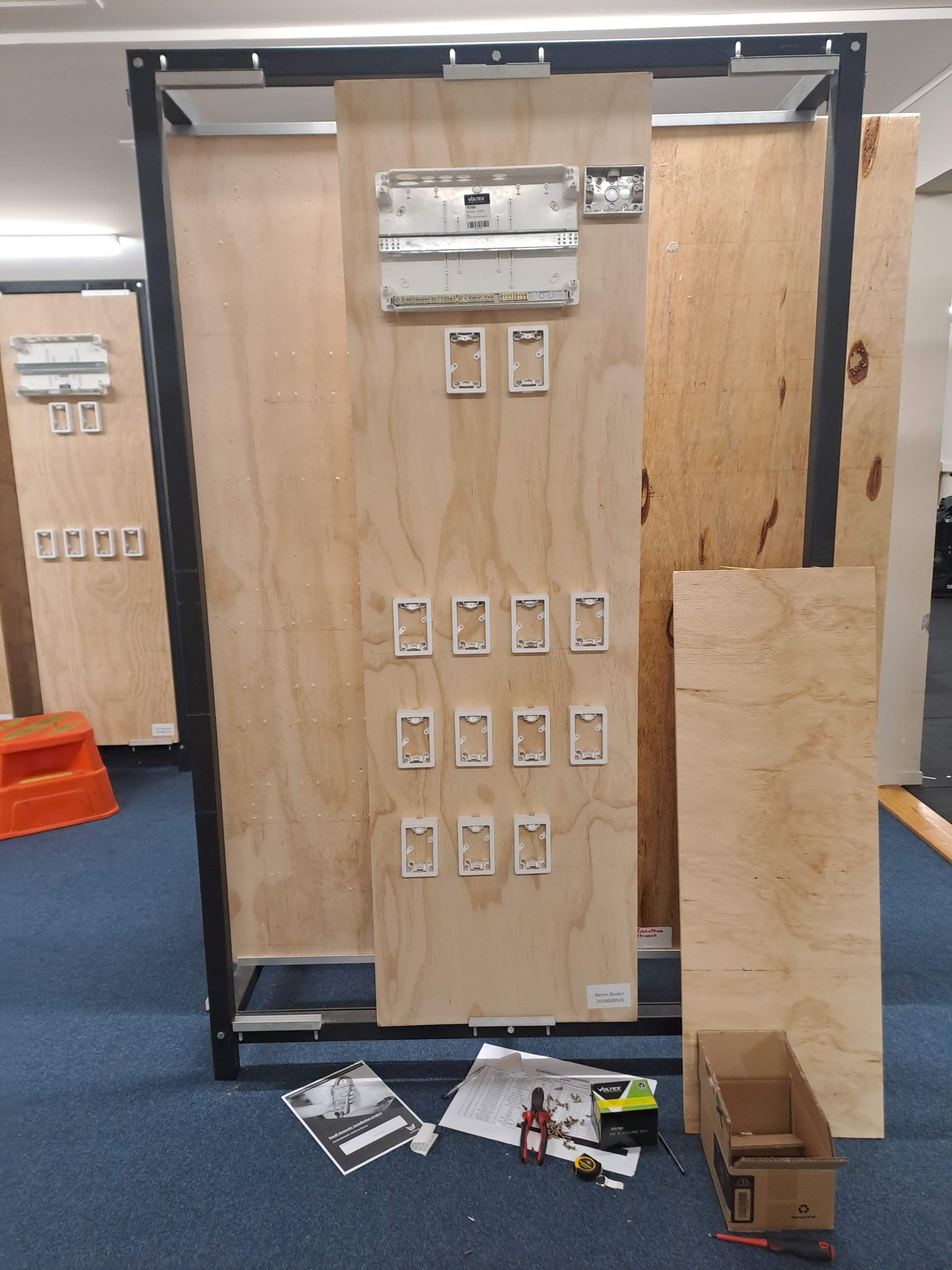
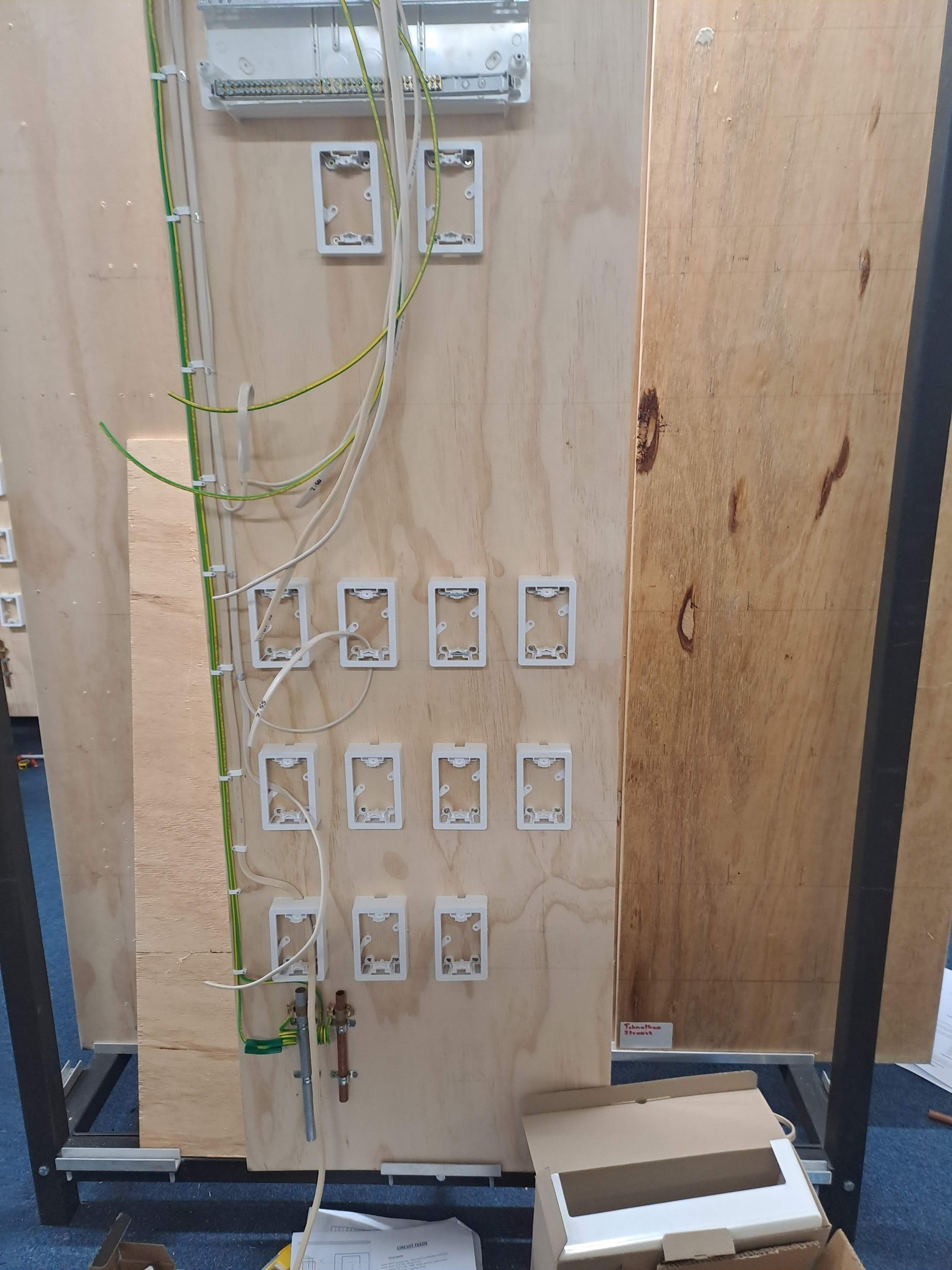
I then terminated each circuit based on diagrams that showed how to wire one-way switches, 2-way switches, intermediate switches, light fixtures, and power outlets.
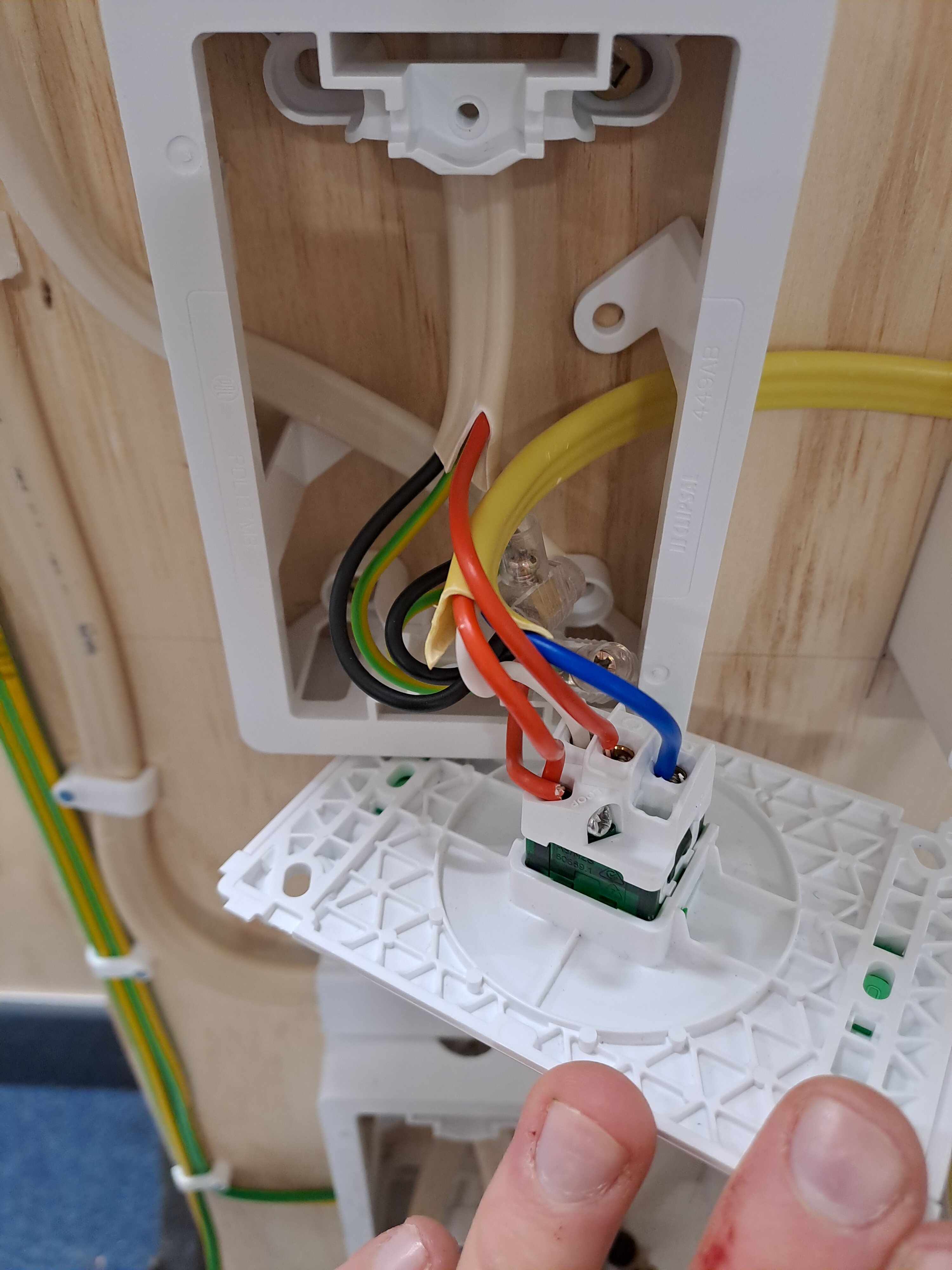
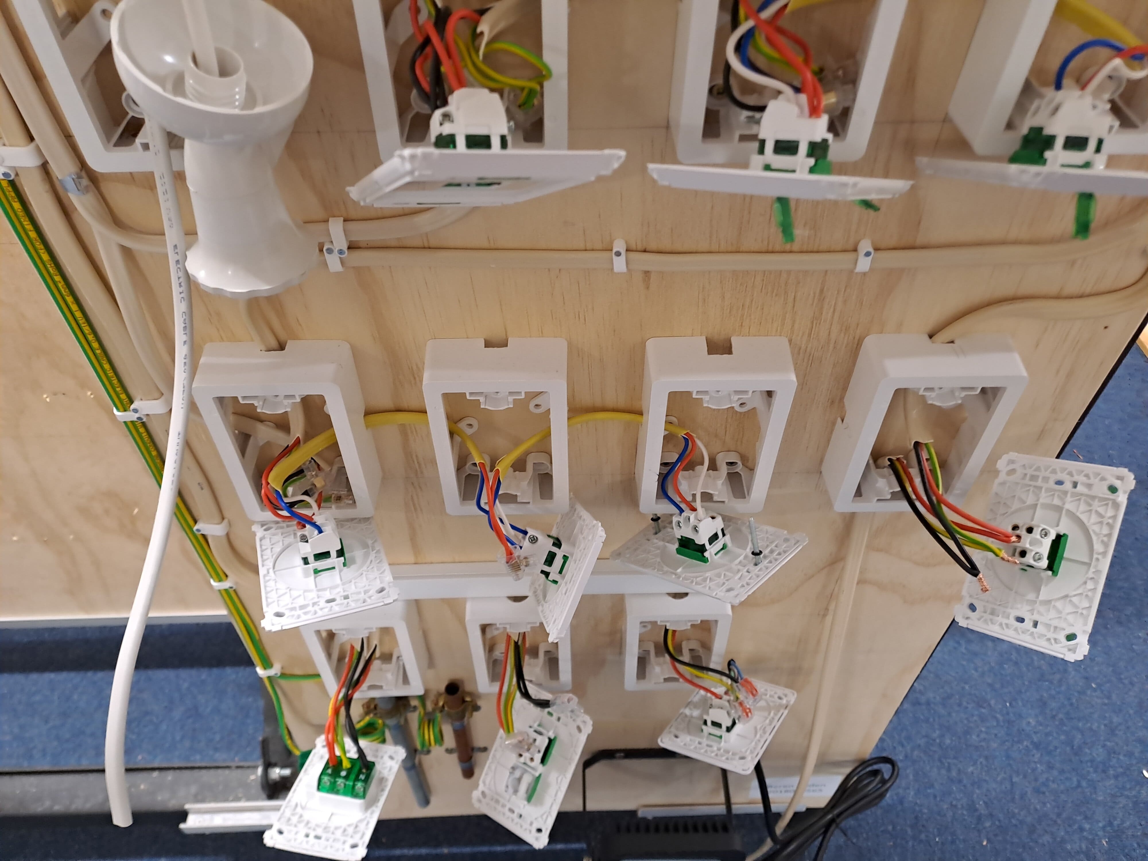
We connected this all back to the appropriately rated MCBs and connected these MCBs to RCDs for residual current protection. I connected the earth cables coming from each circuit back to the earth busbar, then this connected to the earth stake and copper water pipe, and then out to the power source. It was similar with the phases of each circuit being connected to the appropriate MCBs, then I connected this all together in the switchboard with conduit wire and terminated the neutrals back to the neutral busbars and back to the appropriate RCDs.
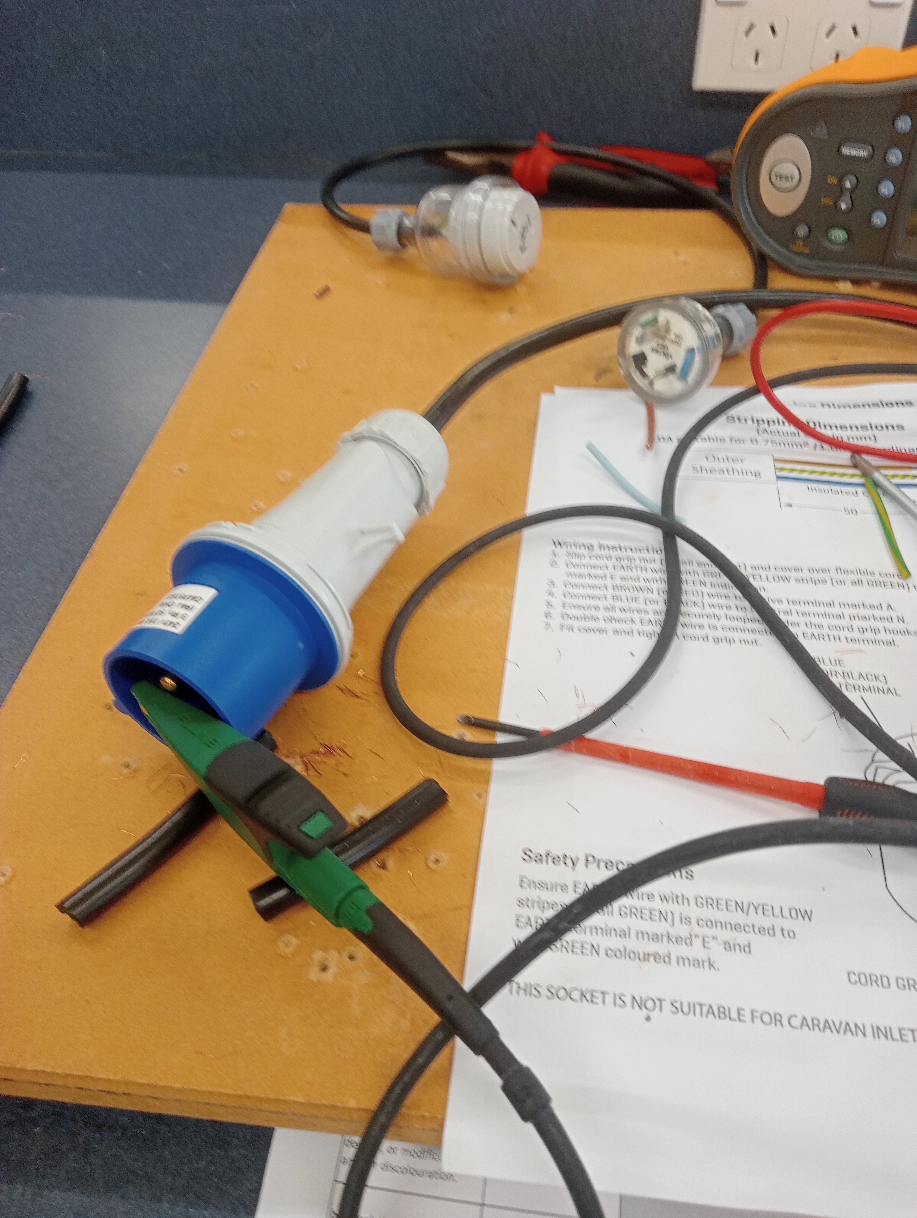
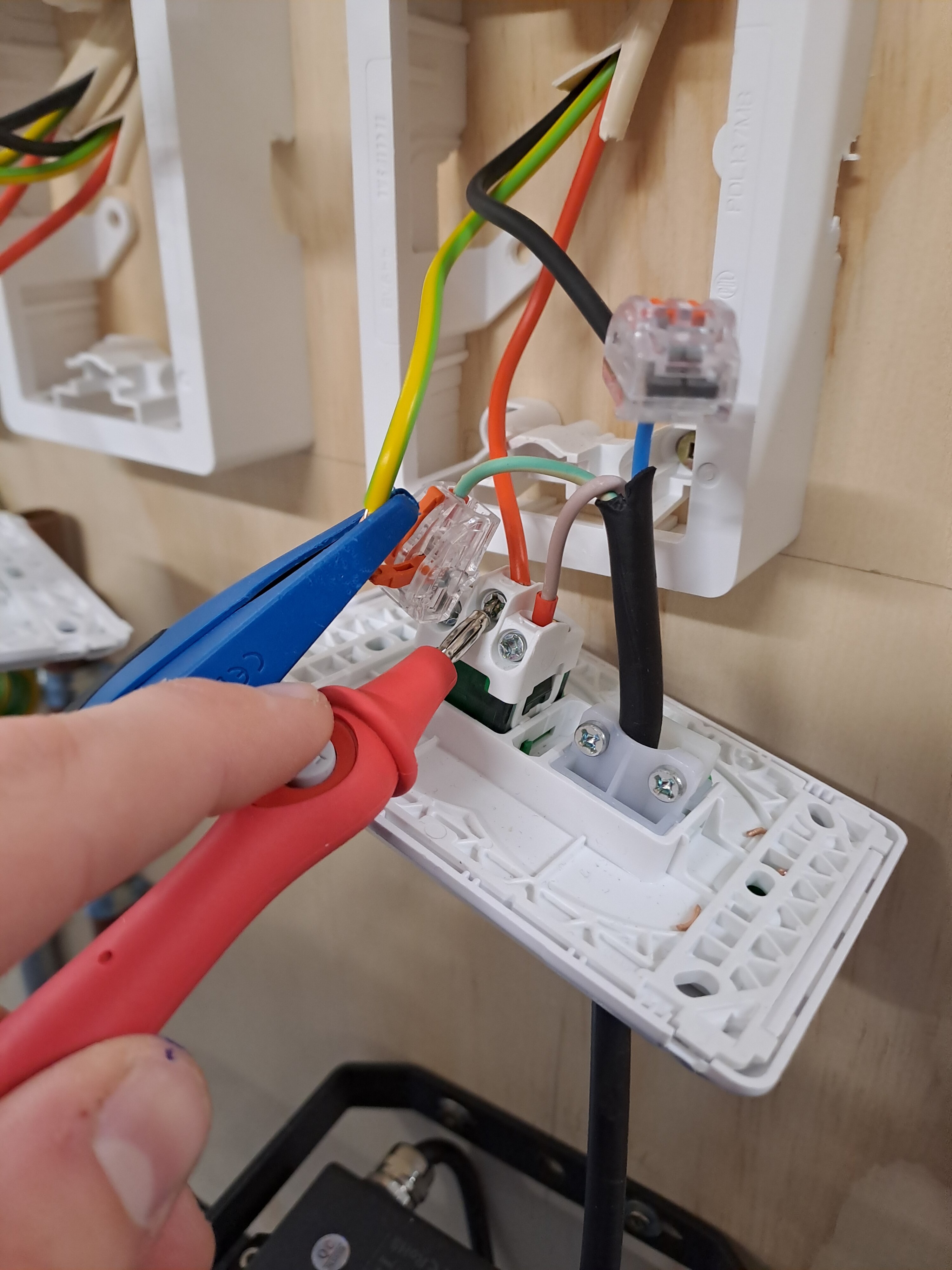
The photograph below shows an earth fault loop impedance test which had the phase and earth shorted and tested on the circuit that was furthest away and had the same connected earth and phase with the fluke multifunction tester on continuity mode. The value in Ohms had to be lower than the allowed value stated in AS/NZS 3000:2007 clause 8.3.9 depending on the value of the MCB.
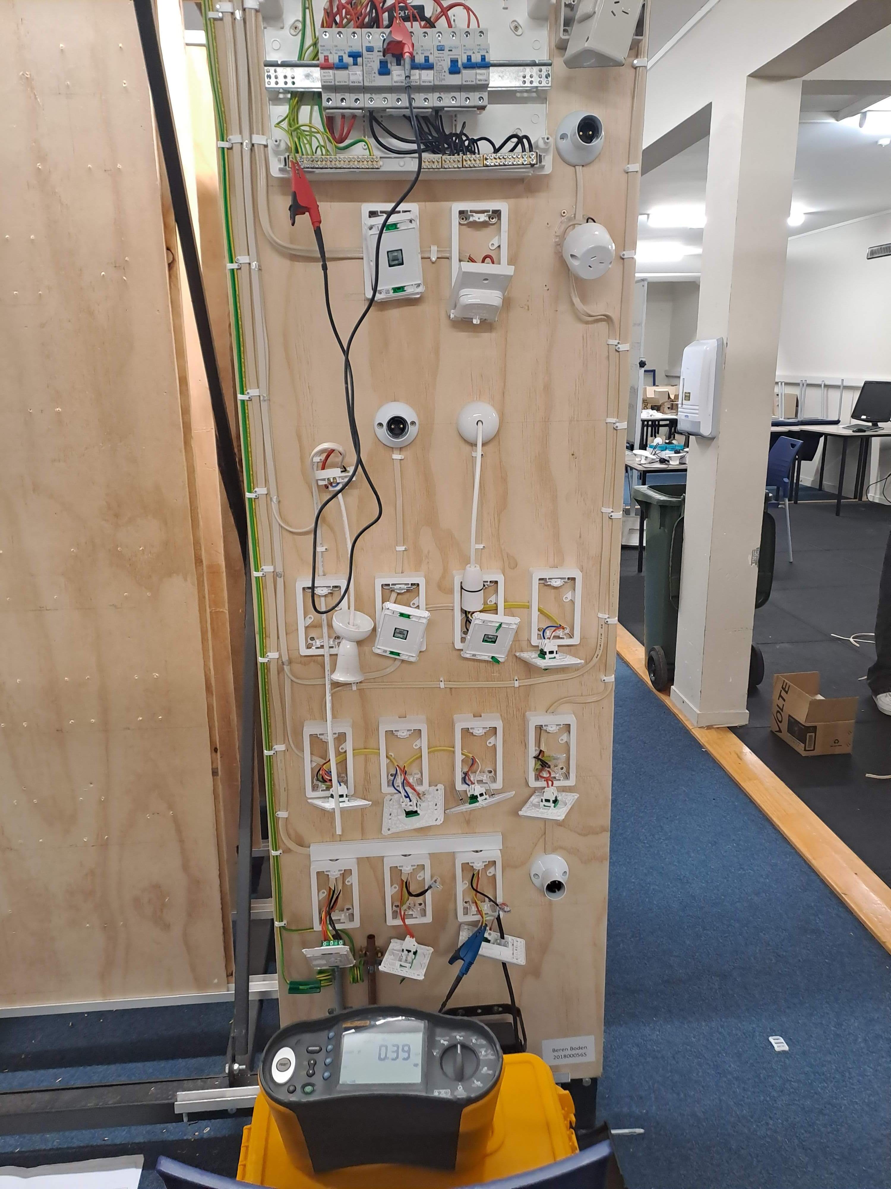
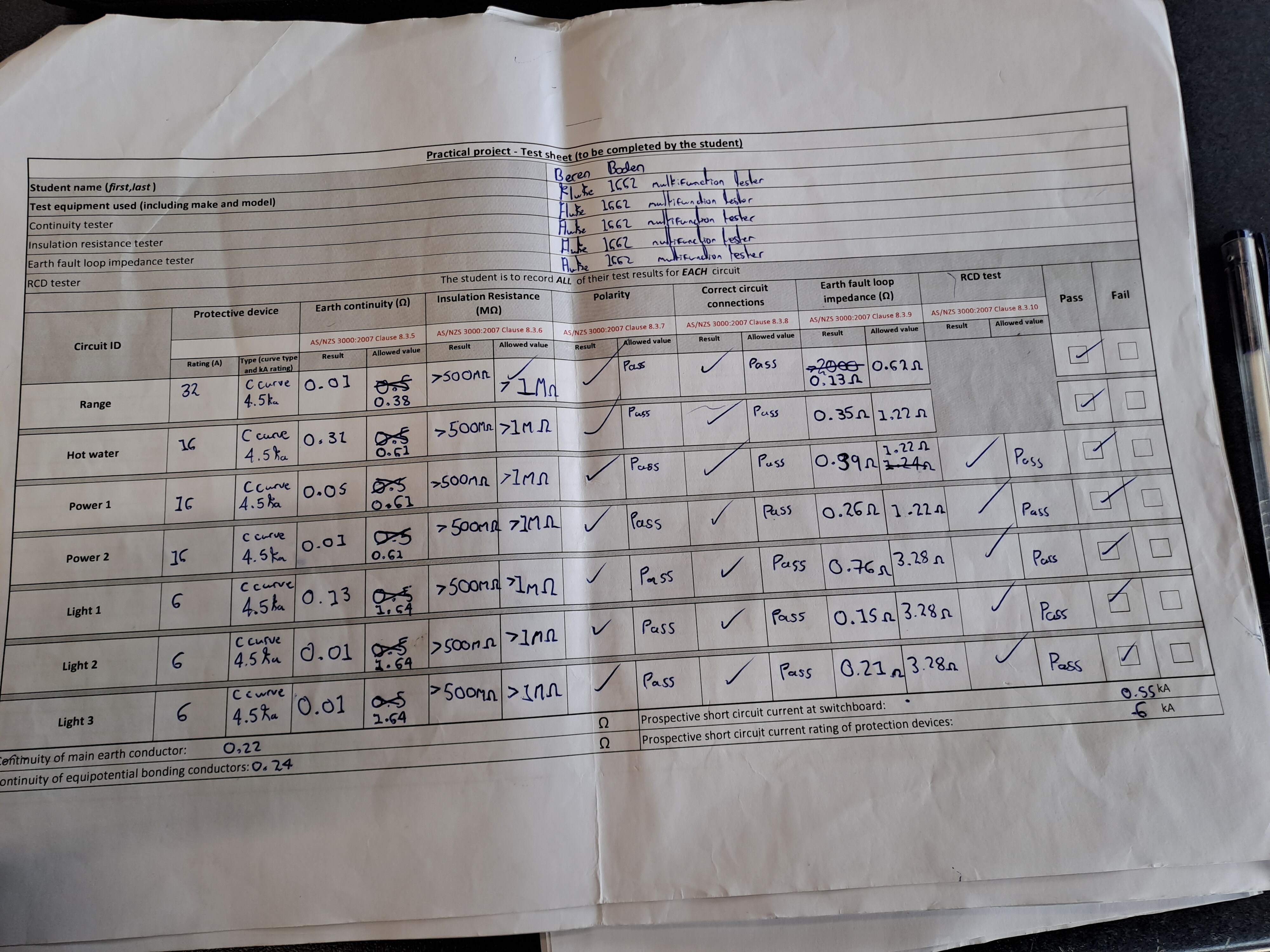
After all tests were completed, we were instructed to screw the covers of all circuits on to be livened on an isolating transformer.
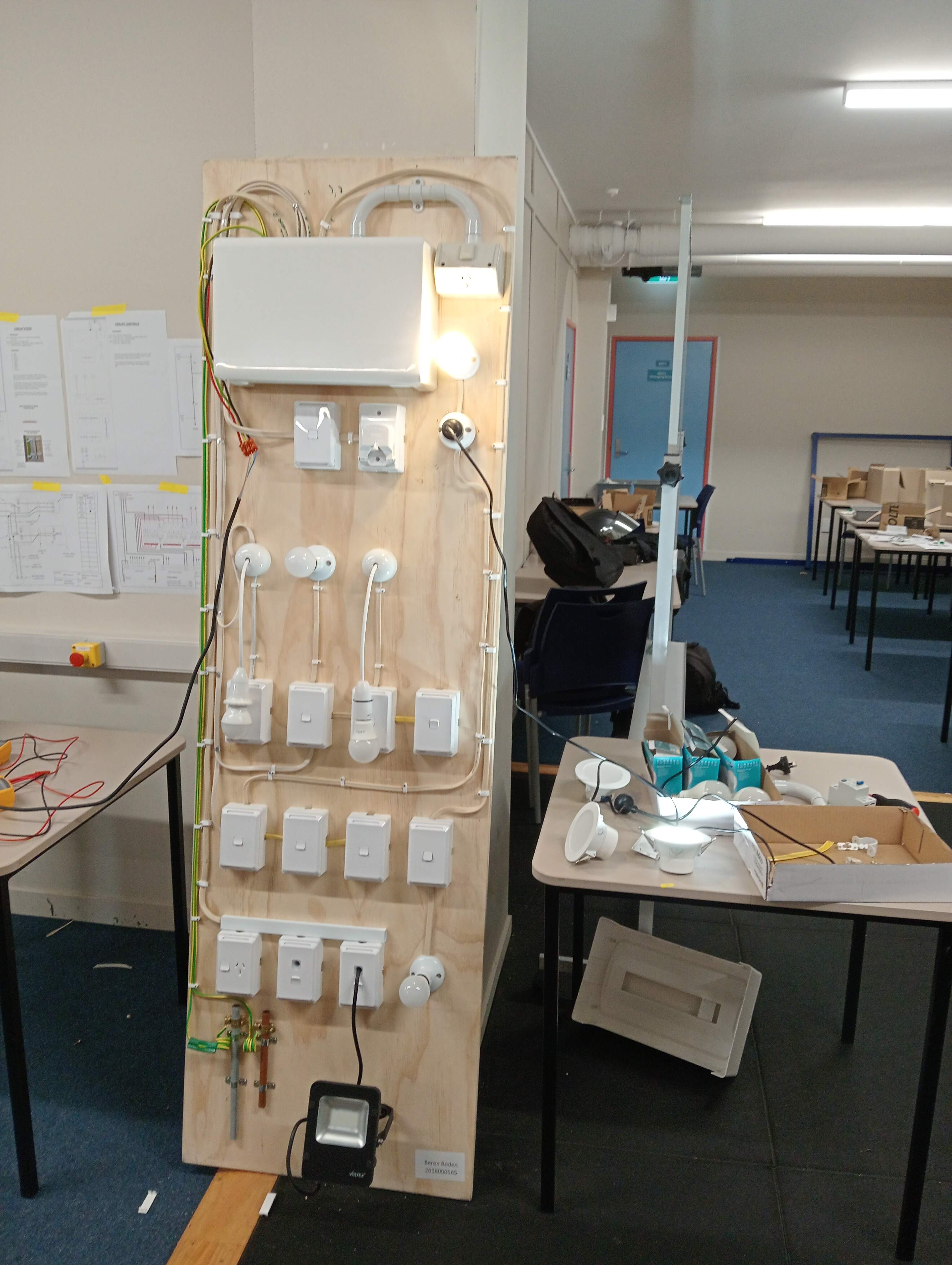
We then tested our boards on an isolating transformer connected to live mains. Every connection in my circuit functioned correctly except for 2 phase conduit wires which I had accidentally swapped around into different MCBs, most likely when I was conducting the earth fault loop impedance test. I re-arranged these connections and my entire circuit worked as expected, with all one-way switches, 2-way switches, intermediate switches, light fixtures, and power outlets working and having the correct voltage when checked with volts AC on a Fluke 115 multi-meter.
Installations
In this course we learned about safe practices in damp environments, cable and cord installation, cable support systems, electronic components, and soldering techniques, making sure to comply with industry standards and legislative requirements.
We learned about IP ratings and zone classifications, legislative requirements for cables and cords, routing methods, and proper handling and installation techniques. Termination methods, such as using crimp lugs and terminal posts.
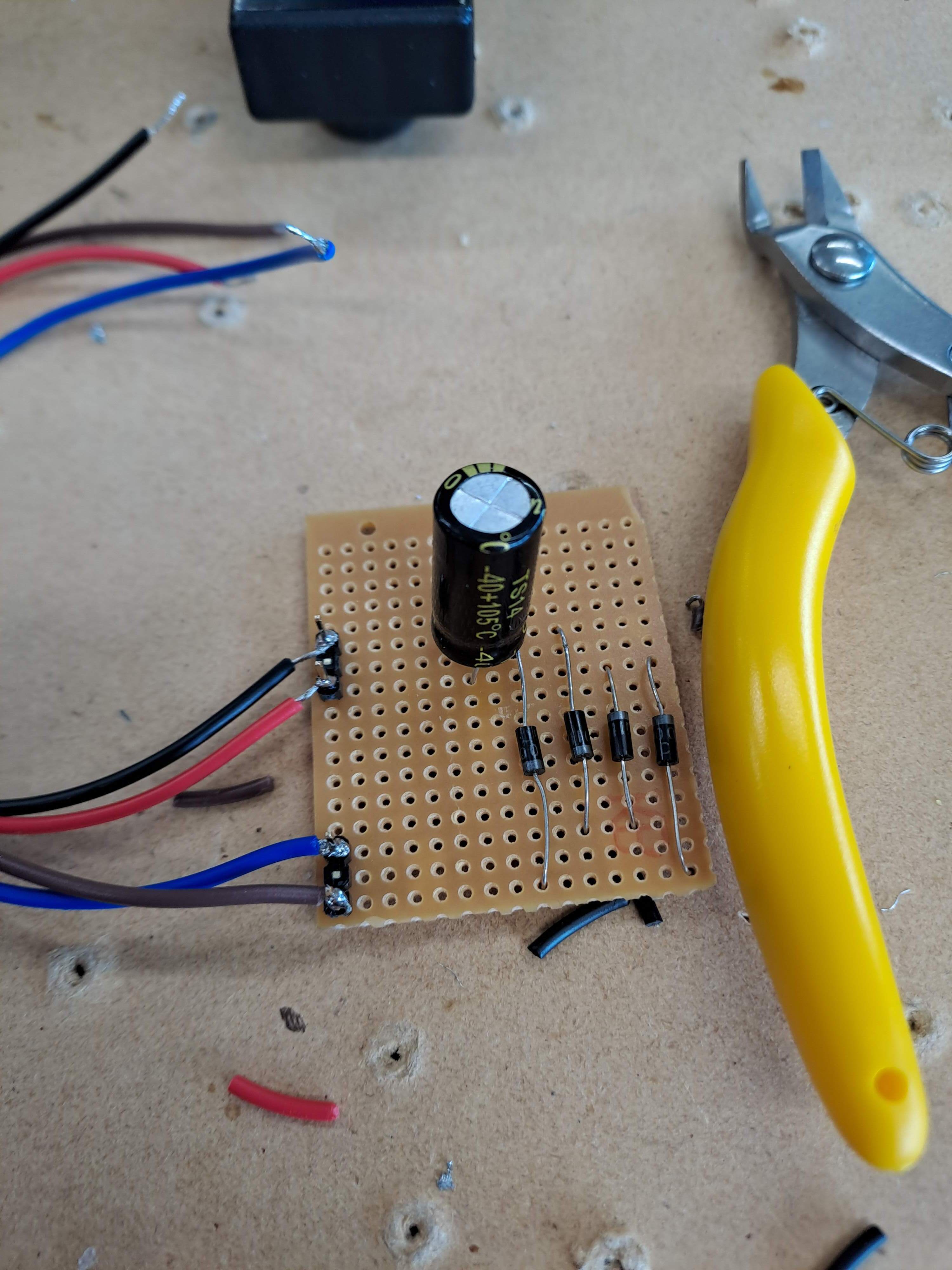
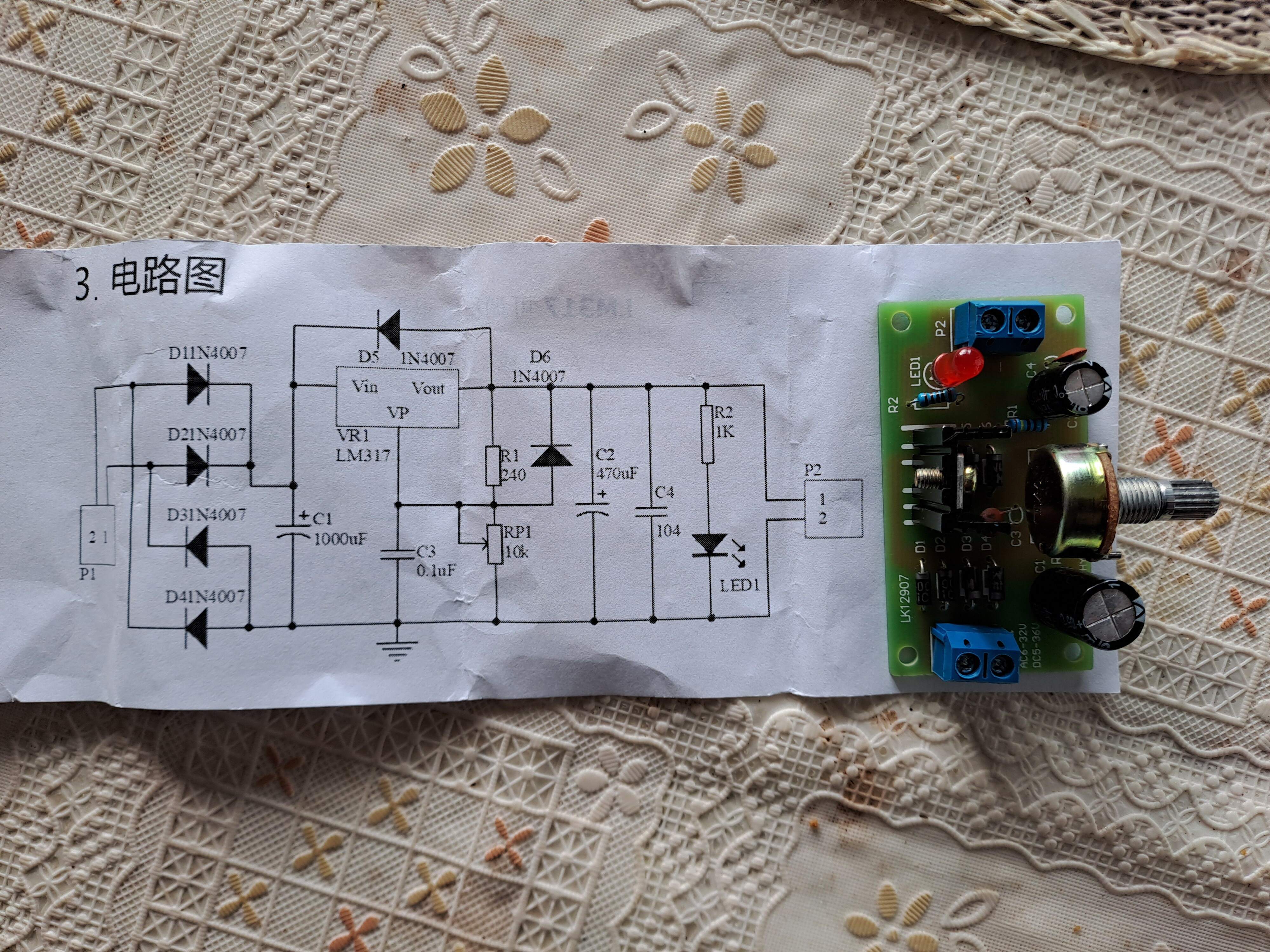
The last practical in this course was a soldering assessment where we had to solder a full wave bridge rectifier and a variable voltage supply which took in 6 - 32V AC or DC and allowed you to control the output voltage with a potentiometer.
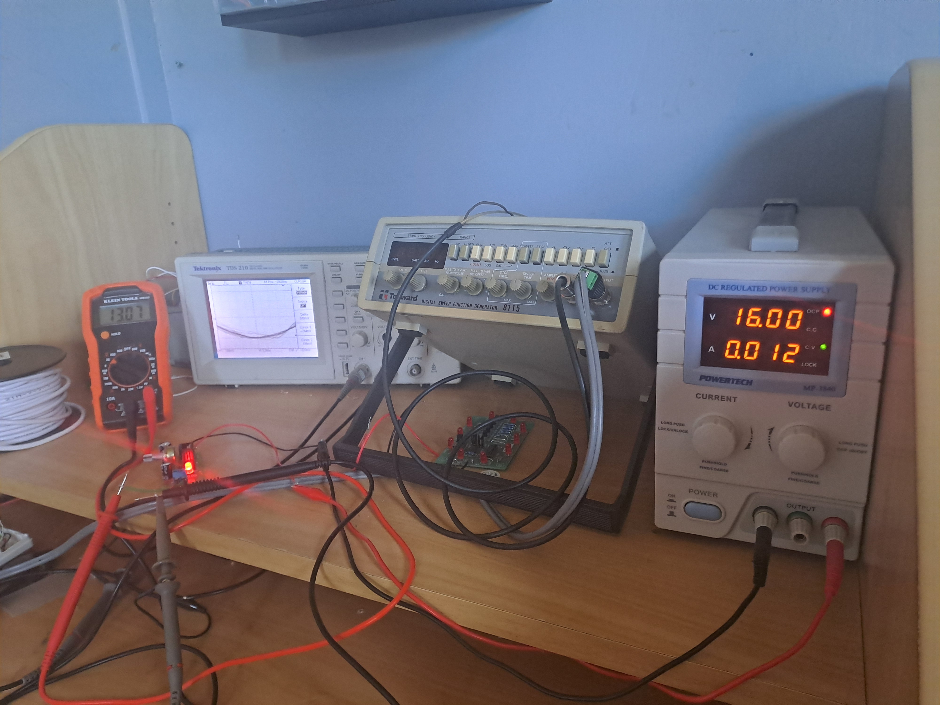
I hooked this variable voltage supply up to my oscilloscope and tried to measure the positive output on channel one of the scope to see the DC output wave
Transformers, Electrical Machines, and Isolation
This course was very theory involved, it covered capacitance and inductance in single-phase motors, single-phase transformers, AC induction motors, and isolation procedures for electrical machinery.
I studied single-phase motors and their applications in household appliances, fans, pumps, and tools. I learned about the different types, including split-phase, capacitor start, and shaded pole motors, and how their components—like the frame, stator, rotor, bearings, and capacitors—contribute to their function.
I learned how transformers convert AC voltage using magnetic fields. Double-wound transformers are safer with separate windings, while autotransformers are smaller and cheaper but less safe. Isolation transformers are used for safety in risky environments without reliable earth connections.
Motor efficiency and transformer performance were also key topics. I looked into how different motor designs balance torque and efficiency, and I examined transformer losses and voltage regulation, which help stabilize voltage for sensitive equipment.
The maths we learned were very helpful in figuring out values for transformer voltage ratios, current ratios, and ratings.
Transformer Voltage Ratio:
Vp/Vs = Np/Ns, where:
- Vp = Primary Voltage
- Vs = Secondary voltage
- Np = Number of turns in the primary winding
- Ns = Number of turns in the secondary winding
Transformer Current Ratio:
Is/Ip = Np/Ns, where:
- Ip = Primary current
- Is = Secondary current
Transformer Rating:
Ip = VA/Vp
Is = VA/Vs, where:
- VA = Volt-ampere rating
I practiced procedures for commissioning electrical circuits, including isolation checks, safety inspections, and functional testing to ensure proper operation. I learned about testing methods like earth continuity and insulation resistance and about issuing certifications such as Electrical Safety Certificates and Certificates of Compliance.
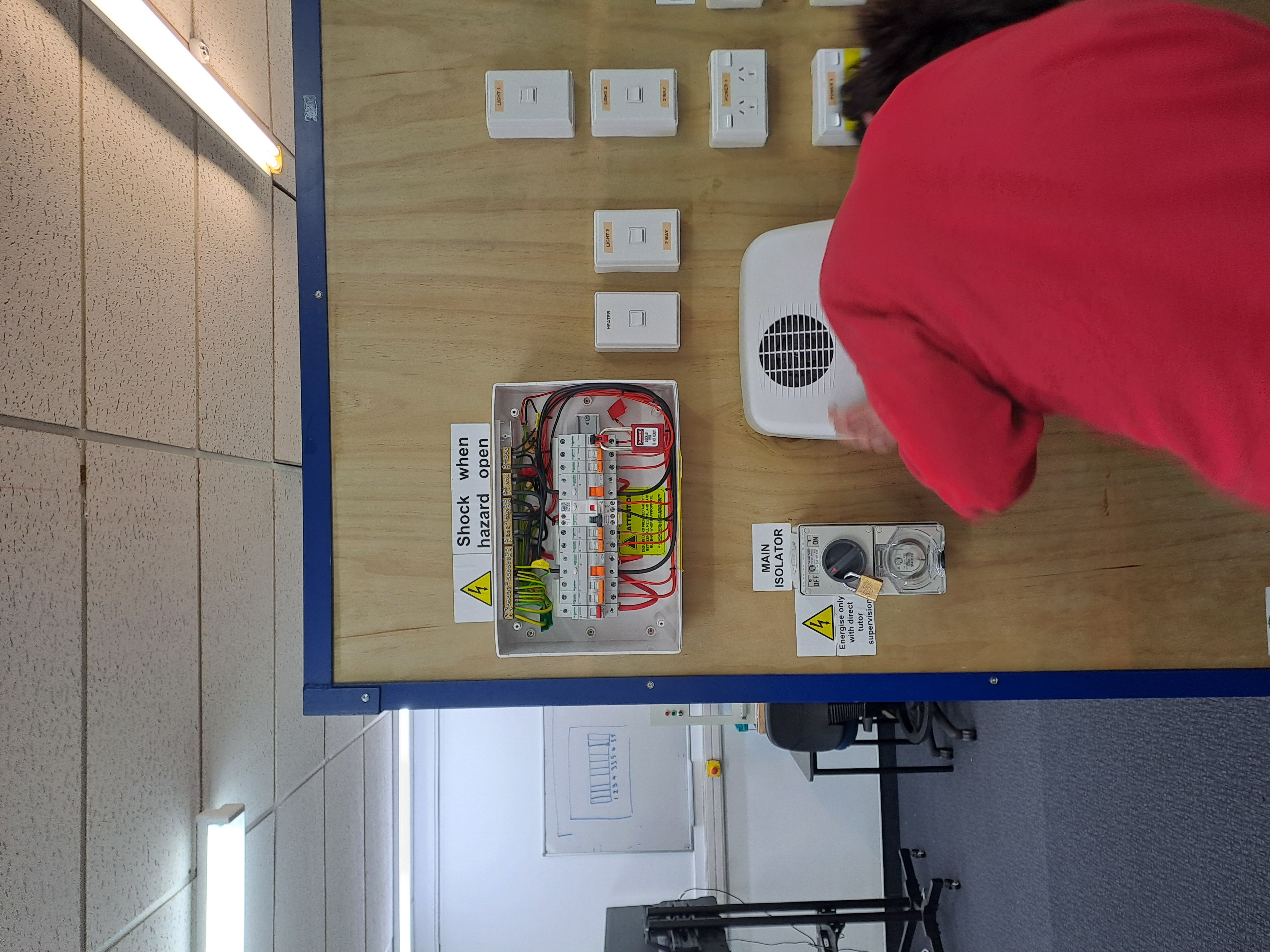
The photo below showed two of us replacing a faulty wall heater and using prove-test-prove on a known live source to ensure our multi-meter is functioning correctly, then doing the correct testing methods on the MCB for the wall heater, like earth continuity, insulation resistance, and polarity checks. This is related to decommissioning, and practicing safely removing electrical fittings and terminating circuits to prevent hazards.
Capstone assessment
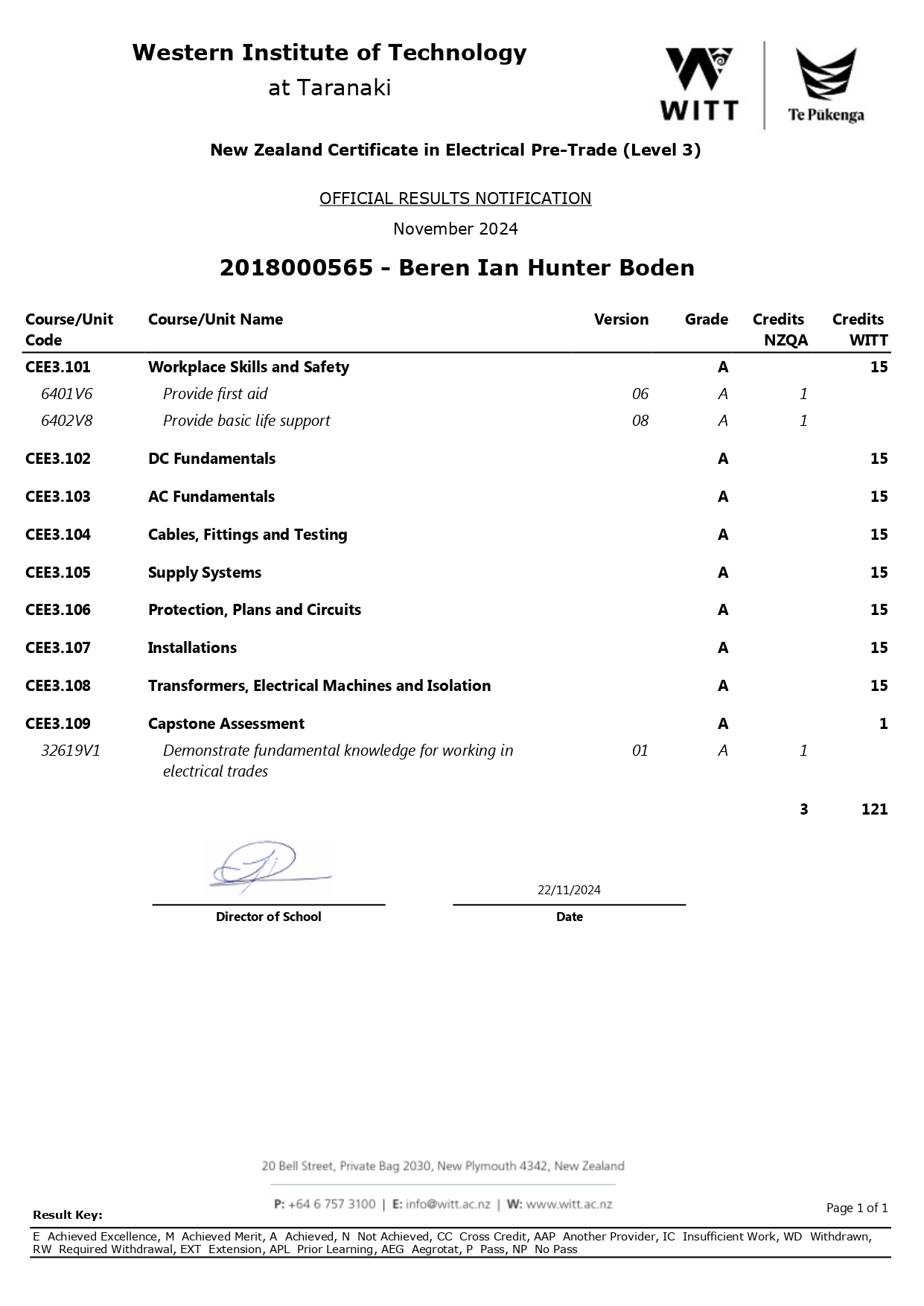
The final end-of-year exam required us to sit and answer 50 questions about everything we learned throughout the year, I passed with a score of 47/50.
Conclusion
With all this knowledge and learning material we went through over the course of 8 months and 8 days, I can say that I have the foundational knowledge required to start a career in the electrical/security industry, during my time studying I was offered an awesome opportunity with Advanced Security as a Junior Security Technician to work 2 days out of the week when I was not at school, and full-time during the school holidays.
It has been great to work in the industry and see what it's like to be an electrician and a security technician, I am enjoying being a security technician, and I am looking forward to starting a career in this field.
Overall, I prefer low-voltage security tech work because it aligns well with my background in IT, programming, and networking. Security involves installing and maintaining systems like alarms, access controls, and CCTV, which rely on understanding networks and integrating hardware with software. My skills in troubleshooting, configuring devices, and working with networked systems make security tech a good fit for me while still complementing the practical skills I gained in electrical work.
What I would like to learn more about, is how commercial buildings are constructed, the different materials used, how to penetrate firewalls, and running cable in these buildings efficiently. Most importantly, how to make the best use of rooms/areas, and access zones to allow people authorized to use these buildings to effectively utilize the security and make it easy for them to get in and out, and create practical schedules for people, even on unusual dates and special events. Helping with the maintenance in the Central District police stations, I can see how crucial it is to have high security, and well thought out zones in high risk sites, this is something I need to know more about and will hopefully develop better awareness of once I have completed my apprenticeship.
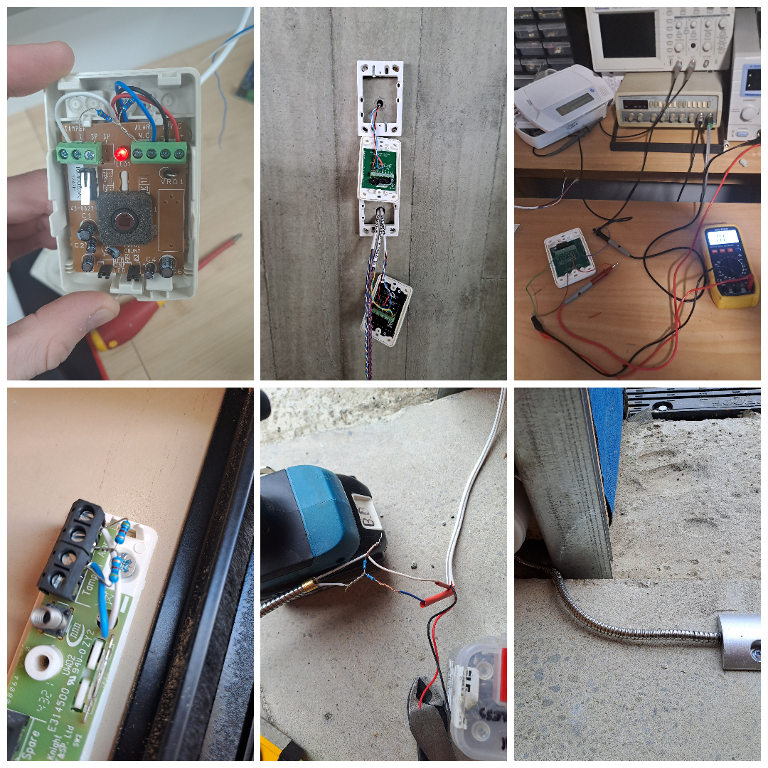
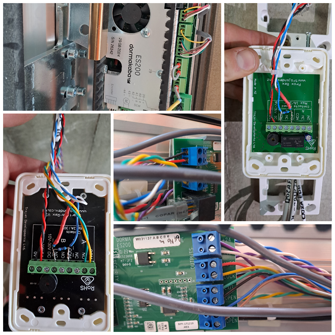
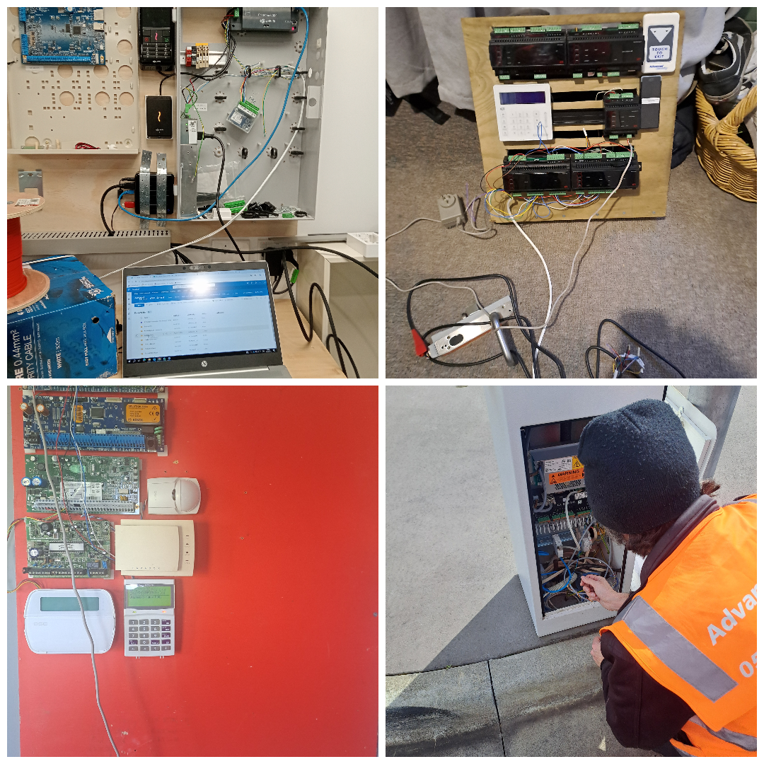
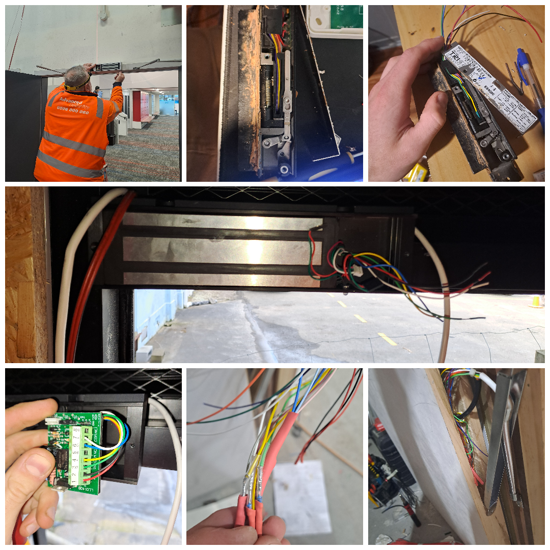
Thanks for reading, here's a few collaged photos of my work as a security tech work, I've learned so much from my three workmates who are great at what they do, and have really helped me understand how to be effective as a security technician.
So far, these are the technologies I have used/installed/learned about;
Locks:
- mag clamps
- electronic mortise locks
- doormakaba es200 auto door
- strike locks
Dry contacts:
- EDRs
- REXs
- PIRs
- Reed switches
CCTV:
- Avigilon cameras
- Axis cameras
- Dahua cameras
- Hikvision
Access control:
- Inner range: inception, integriti
- Tecom: Challanger
- Gallagher: Controller 6000
- Protege: WX, GX
Alarms:
- Bosch: 880, 6000, 16i, 3000, solution 64
- DSC: Neo, powerseries
- Paradox
