For understanding routing protocols I wanted to create a network scenario focusing on routing protocols using Packet Tracer. This article will cover concepts of distance vector protocols including RIP, link state protocols including OSPF and lastly I will be covering the hybrid protocols EIGRP, and BGP.
RIP (Routing Interface Protocol v1 & v2)
Let's first start with the most basic protocol RIP, it is a distance vector routing protocol and uses hop counts to determine the best route between a source and destination network. The maximum number of hops before a packet is discarded is 15. RIP has a default AD (administrative distance) of 120.
Here is a basic RIP configuration with two networks, the WAN network has been set to a 10.0.0.0/8, and the sub networks have been set to 192.168.0.0/24.
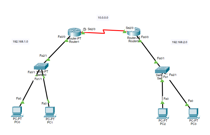
In order to get this configuration, I had to configure both routers in the CLI. Router 1 is the DCE (data communication equipment) in this case and I have set the clock signal, the clock signal, set on the DCE, is crucial for synchronizing data transmissions. It establishes a common timing reference, dictates data transfer speed, and ensures reliable communication between network devices.
Router CLI configuration These are the commands I entered into Router 1;
R1(config)#Enters global configuration mode, which allows the configuration of system-wide settings.R1(config)# int fa0/0Enters the interface configuration mode for the Fast Ethernet 0/0 interface.R1(config-if)# ip address 192.168.1.1 255.255.255.0Assigns an IP address of 192.168.2.1 and a subnet mask of 255.255.255.0 to the Fast Ethernet 0/0 interface for the default gateway.R1(config-if)# no shutActivates the Fast Ethernet 0/0 interface.R1(config-if)# int serial 0/0/0Enters the interface configuration mode for the Serial 0/0/0 interface.R1(config-if)# ip add 10.0.0.1 255.0.0.0Assigns an IP address of 10.0.0.1 and a subnet mask of 255.0.0.0 to the Serial 0/0/0 interface.R1(config-if)# no shutActivates the Serial 0/0/0 interface.
I then have configured Router 2 with similar commands;
R2(config)#- `R2(config)# int fa0/0
- `R2(config-if)# ip add 192.168.2.1 255.255.255.0
- `R2(config-if)# no shut
- `R2(config-if)#
- `R2(config-if)# int serial 0/0/0
- `R2(config-if)# ip add 10.0.0.2 255.0.0.0
- `R2(config-if)# no shut
PC configuration
Subnet one:
PC1IP address: 192.168.1.2 Subnet mask: 255.255.255.0 Default Gateway 192.168.1.1
PC2: IP address: 192.168.1.3 Subnet mask: 255.255.255.0 Default Gateway 192.168.1.1
Subnet two:
PC1: IP address: 192.168.2.2 Subnet mask: 255.255.255.0 Default Gateway 192.168.2.1
PC2: IP address: 192.168.2.3 Subnet mask: 255.255.255.0 Default Gateway 192.168.2.1
Configure RIPv2 on both routers
Router 1
R2(config)# router rip
R2(config-router)# version 2
R2(config-router)# network 10.0.0.0
R2(config-router)# network 192.168.1.0
Router 2
R2(config)# router rip
R2(config-router)# version 2
R2(config-router)# network 10.0.0.0
R2(config-router)# network 192.168.2.0
Now RIP has been enabled on both routers, after which you should wait at least 25 seconds before sending packets, as that is how long it takes RIP to update its routing table. Now you can successfully ping PC1 on 192.168.2.2 from PC1 on 192.168.1.2.
If you use the show ip route command on router 1, you can see that RIP is successfully enabled and working.
Router>show ip route
Codes: C - connected, S - static, I - IGRP, R - RIP, M - mobile, B - BGP
       D - EIGRP, EX - EIGRP external, O - OSPF, IA - OSPF inter area
       N1 - OSPF NSSA external type 1, N2 - OSPF NSSA external type 2
       E1 - OSPF external type 1, E2 - OSPF external type 2, E - EGP
       i - IS-IS, L1 - IS-IS level-1, L2 - IS-IS level-2, ia - IS-IS inter area
       * - candidate default, U - per-user static route, o - ODR
       P - periodic downloaded static route

Gateway of last resort is not set

C 10.0.0.0/8 is directly connected, Serial2/0
C 192.168.1.0/24 is directly connected, FastEthernet0/0
R 192.168.2.0/24 [120/1] via 10.0.0.2, 00:00:08, Serial2/0
You can see that router 1 has learned about the 192.168.2.0/24 network. The letter R indicates that the route was learned using RIP. Note the administrative distance of 120 and the metric of 1 where it has [120/1].
EIGRP (Enhanced Interior Gateway Routing Protocol)
Enhanced Interior Gateway Routing Protocol (EIGRP) is a Cisco proprietary, advanced distance vector routing protocol. Combining characteristics of both distance vector and link-state protocols, EIGRP offers powerful features including support for IP, IPv6, Variable Length Subnet Masking (VLSM), and discontiguous networks. It effectively utilizes the Reliable Transport Protocol (RTP) for communication and implements the Diffusing Update Algorithm (DUAL) for optimal path selection. With its capability to maintain detailed tables—Neighbor, Topology, and Routing tables—it provides an efficient way to manage routes, including successor and feasible successor routes, making it highly suitable for large networks.
Here is a simple EIGRP network created in Packet Tracer.
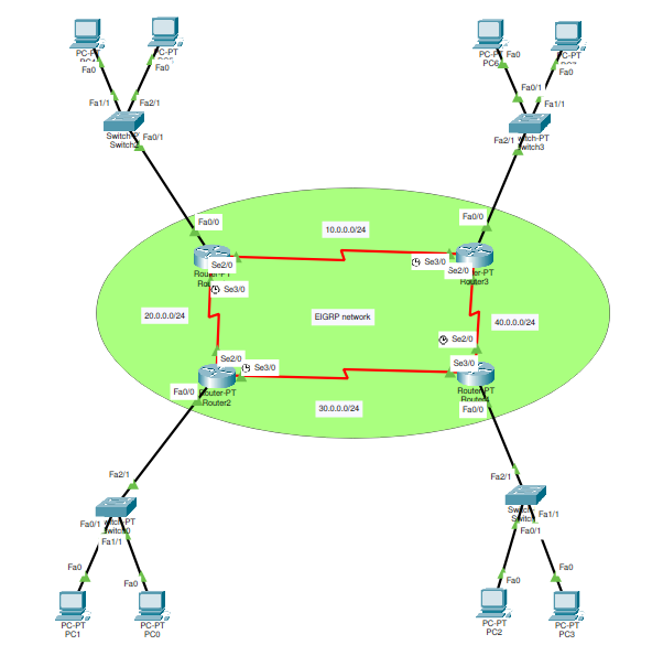
Let's begin by understanding our network design. We have four routers, each connected to an internal LAN network (192.168.1.0, 192.168.2.0, 192.168.3.0, 192.168.4.0) with two PCs and a switch. These routers are interconnected via WAN links (10.0.0.0, 20.0.0.0, 30.0.0.0, 40.0.0.0).
To configure EIGRP, I moved into global configuration mode on each router, then initiated EIGRP with the Autonomous System number 1. Subsequently, network statements were added for each specific network.
An instance of such configuration on the first router is as follows:
router eigrp 1
network 192.168.1.0
network 10.0.0.0
network 20.0.0.0
The command router eigrp 1 in EIGRP initiates the routing protocol with the Autonomous System (AS) number as 1. This number is vital as it identifies a group of routers within the same routing domain. It's crucial that each router within this domain shares the same AS number; otherwise, routers with different AS numbers will not exchange routing information or establish neighbor relationships. This command is thus fundamental in maintaining the consistent propagation of routing information across the network, ensuring its efficient functionality.
This process was then replicated on the remaining routers, modifying the networks as necessary.
To validate the configuration, I used the command show ip eigrp neighbors on each router. This allowed me to confirm the formation of the EIGRP neighbor relationships. Additionally, by utilizing the show ip route command, I could review the routing table, identifying routes learned via EIGRP, indicated by the 'D' code.
A vital part of the process was verification through testing. I performed ping operations from one PC to another across different networks. The successful ping results confirmed the validity and efficiency of the EIGRP configuration.
OSPF (Open Shortest Path First)
//TO be continued
IS-IS (Intermediate Systems to Intermediate Systems)
//TO be continued